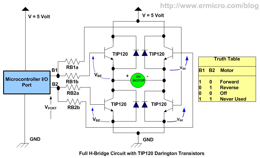

Investigating the schematic shown in Fig. As a consequence the peak of the ripple current through the motor ends up being half of the one found for the bipolar case, thus leading for lower losses in the motor itself One of the major difference with the bipolar drive scheme is the fact that the voltage across the motor will have an amplitude of only V DC. In this case a proper dead-time constraint must be respected. In order to decrease the loss caused by the diode voltage drop, Q1 can be switched ON while Q3 is OFF. If we assume Q3 switching and Q2 turned ON, then when the former is switched OFF the current will flow through Q1 body diode. For the same reason described in the bipolar drive some current will be forced to flow through one of the MOSFETs body diode when the switching MOSFET is turned OFF, see Fig.
#FORWARD AND REVERSE MOTOR H BRIDGE DRIVER#
In its simplest form it allows for the elimination of the dead time which reduces the complexity of the driver circuit. The unipolar drive scheme, instead, allows for the current to be regulated by keeping ON one right side MOSFET (Q2 or Q4) while switching only one left side MOSFET(Q3 or Q1). More information about how some of the constants were determined for an example DC motor will be given later. This may be found using the motor data sheet or by measurement. 3 below:Īs it is considered that the torque and back EMF constants are equal, the following equality may be given: K T = Ke = K.īased on the above equations the motor output torque and speed may be approximated by knowing the motor constants. Moreover, the back EMF is proportional to the rotor velocity dθ/ dt and the back EMF constant K, as shown in Eq. In this case V is the input voltage to the DC motor and the one supplied by the H-bridge which is formed by 4 MOSFETs within 2 half-bridges in order to obtain bi-directional control.Ĭonsidering the magnetic field as constant, the torque produced by the DC motor will thus be proportional to the armature current and the motor torque constant K T. Taking these into consideration and applying some circuit analysis techniques such as Kirchhoff’s voltage law, gives Eq. Moreover, the rotor mechanical constants are also shown as: motor torque (T), rotor angle (θ) and rotor inertia (J).

This contains its electric resistance (R a), inductance (L a) as well as back EMF (e). Considering the inner structure of the DC motor one can consider its armature circuit, (as can be seen in Fig.4). This shows that the rotational speed of this particular motor is 103.2 rad/s. In simulation 1, a DC motor is connected to a DC voltage source of 5 V. The direction of motor rotation can be controlled using only one MOSFET, while the other MOSFET can be switched by PWM to control the motor current.

2 b) is a scheme that directly uses MOSFETs to drive the motor. However, the relay cannot control the current of the motor, so it still needs to be connected to a MOSFET to control the current, so as to meet the functional requirements of anti-pinch.įig. The direction of the motor rotation is selected by the contact of the relay. Therefore more and more manufacturers consider using MOSFETs to replace relays.įig. 2 a) is a motor scheme that mainly uses relays for motor drive. However, compared with relays, MOSFETs have obvious advantages in noise, service life, miniaturization and reliability. Driving a relay is simple, and the internal resistance of the connection can be very low. In modern automotive applications, an average of about 30 relays are used in a car. Relay replacement in a power-folding mirror assembly


 0 kommentar(er)
